This is a post about spending a few days learning about DIY wired networking, covering mostly physical ethernet cable installation in a house.
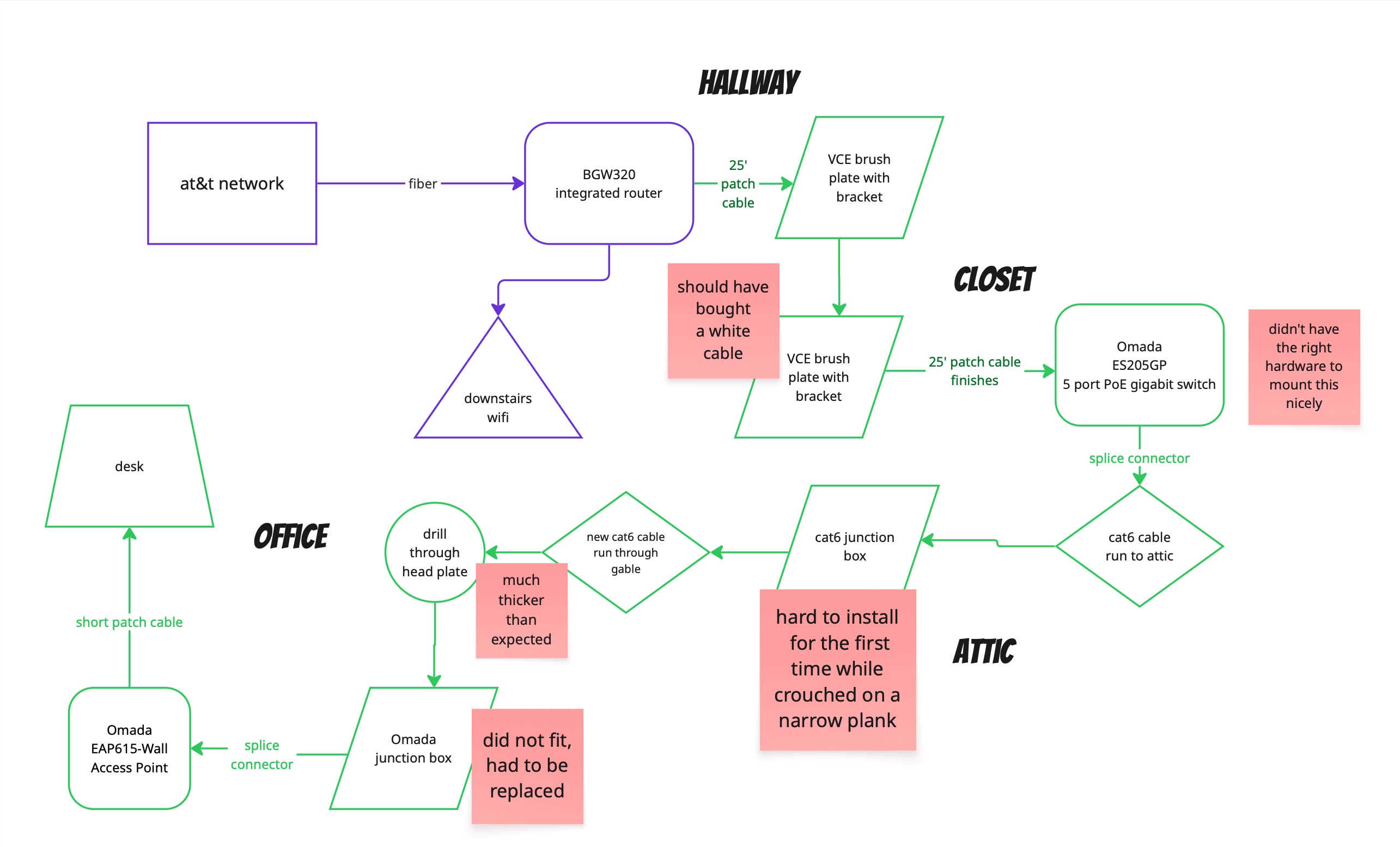
It’s a brain dump of a lot of small details about the project. If you just want the TLDR - the layout diagram sums it up.
Context
I’ve been getting more and more tired of my home wifi getting unreliable during work zoom calls. Sometimes it works perfectly, but sometimes it loses the connection in mid-sentence, causing chaos and miscommunication. I join a lot of zoom calls, and it started to make me feel stressed all the time about the network quality.
We have AT&T fiber, which comes with an all-in-one wireless gateway (WiFi, basic LAN setup, ONT). The problem is that the WiFi signal from this (of course) doesn’t reach the place I need it to reach. (And while AT&T will happily rent you extra home networking gear that might help, I have no intention of renting my own home networking infrastructure, since it isn’t expensive to buy in the first place.)
It all made me daydream about having wired ethernet again. When I was on campus in college and graduate school, there was wired ethernet practically everywhere. The campus ethernet network had practically zero physical connectivity issues that I ever encountered, in 15 years of being around research universities. It pretty much just worked.
I figured: I just want to install one ethernet cable; it can’t be that hard, right? It just has to go up two stories into the attic, cross the attic, and then come down to the right place.
I called a local electrician. He showed up, looked around and said: This job will cost you $1100, and afterwards, I will leave your stairwell full of unpatched holes in the sheetrock. I sensed a slight hint of sexist condescension as well.
I didn’t hire him.
Just buy a WiFi extender, my colleague said. So I tried that as a bandaid, but it was often unreliable.
Meanwhile, I discovered that there were lots of unused Cat 6 cable runs already hidden in my house. It’s a new-ish house, so I assume these cables were installed when it was built and then forgotten. A bunch of them were already routed into the attic, which solved the awkward problem of how to get ethernet to the attic. I guess it’s easy to run cables horizontally in a house, through an attic or basement, but it’s very hard to run them vertically through the walls, so I was glad someone else already did that.
Time passed, calls kept getting dropped, and I kept thinking about wired ethernet.
“You should get mesh networking,” my friend said.
In the end, I thought: why not both?
Layout
Mesh networking works better with what the networking people call “wired backhaul,” meaning that the wireless access points are connected by a wired network to a central router. If I was going to install mesh networking devices, I wanted to have them backed by ethernet cables.
Meanwhile, I tried really hard to imagine exactly how to get a cable from point A to point B through my house. All the pre-existing Cat 6 cables came out into a media distribution box in a closet. I needed to connect the media distribution box to our AT&T gateway. Then I had to splice into one of the existing cables in the attic, run some new cable through about 20’ of unfinished attic space, and finally run it down through the wall and into a low voltage junction box.
I drew a Miro diagram of what needed doing:
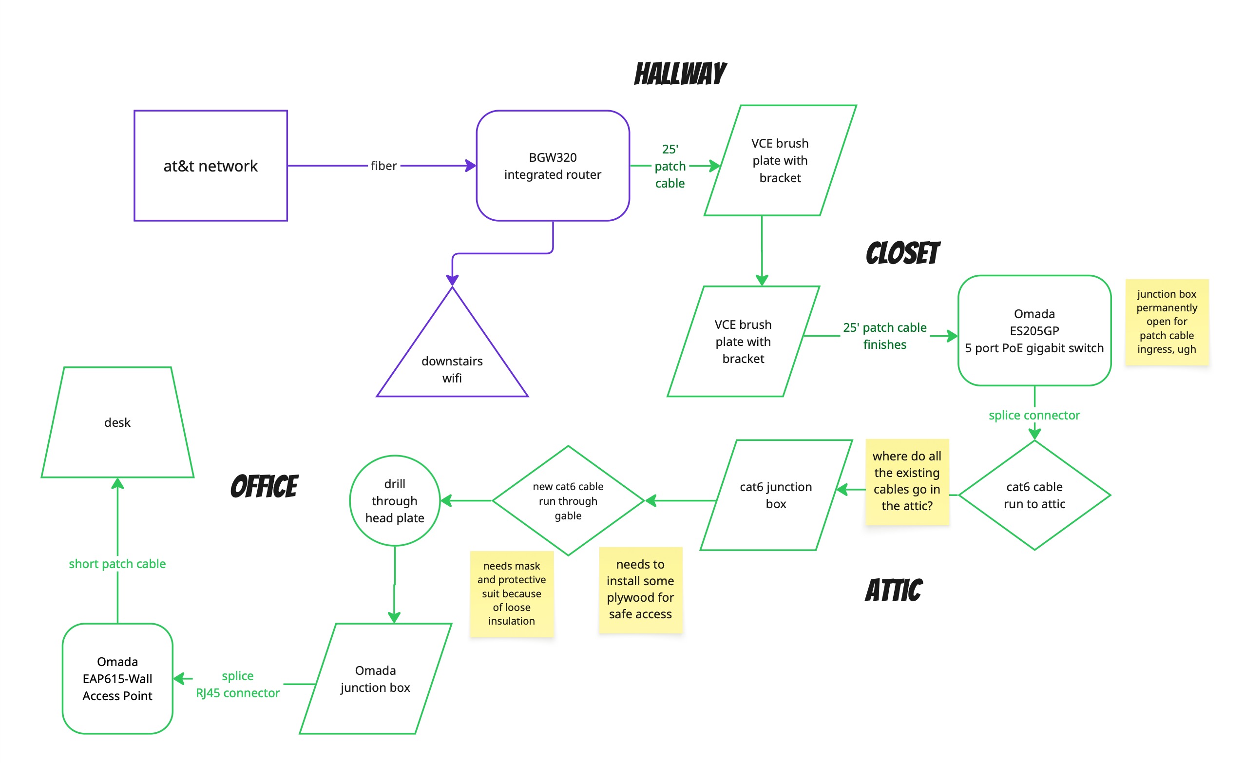
The idea was to set up a very minimal mesh networking setup that was super easy to extend later. I added a gigabit switch and an extra WiFi access point along with the wired ethernet to my workstation, and I prepared the spare ethernet cables for possible use later.
Good enough gear
It’s hard to select gear for this kind of project, if you aren’t familiar with this particular consumer market. There are hundreds of consumer-grade devices you could buy, and it’s hard to know what to rely on. Lots of people give advice, but whose advice do you trust?
In the end, I bought my gear from Omada, the slightly higher-end “prosumer” line of TP-Link networking devices.
I was looking for these kinds of features in a device to put in my office:
- Supports both wired and wireless internet (this is a ubiquitous feature, but it was still important to me).
- Provides WiFi access points that gracefully delegate the networking to an upstream router (it doesn’t create a separate subnet or do DHCP again).
- Uses power over ethernet so you don’t need a separate power supply for the access point.
- Supports mesh networking so you can expand later into a larger setup.
- Allows virtual networking configuration, so you can put certain (untrusted) devices on a separate subnet/vlan if you want.
- Does not require me to buy too much gear up front/easily allows incremental deployment.
You then also need a power supply upstream to supply power over ethernet. It can be part of the switch or separate from the switch, but it’s simple if it’s part of the switch.
I went with an Omada EAP615-Wall Access Point and an Omada ES205GP 5-port gigabit PoE switch.
Good enough tools
I didn’t own any of the right tools to do this project, so I found myself buying a starter network cabling kit from Zoerax. The specific item is called Ethernet Crimping Tool Kit (amazon.com). For what I needed, it was plenty - the crimping tool was fine (it could have been sharper), the wirecutters were excellent, and the network cable tester was basic but functional.
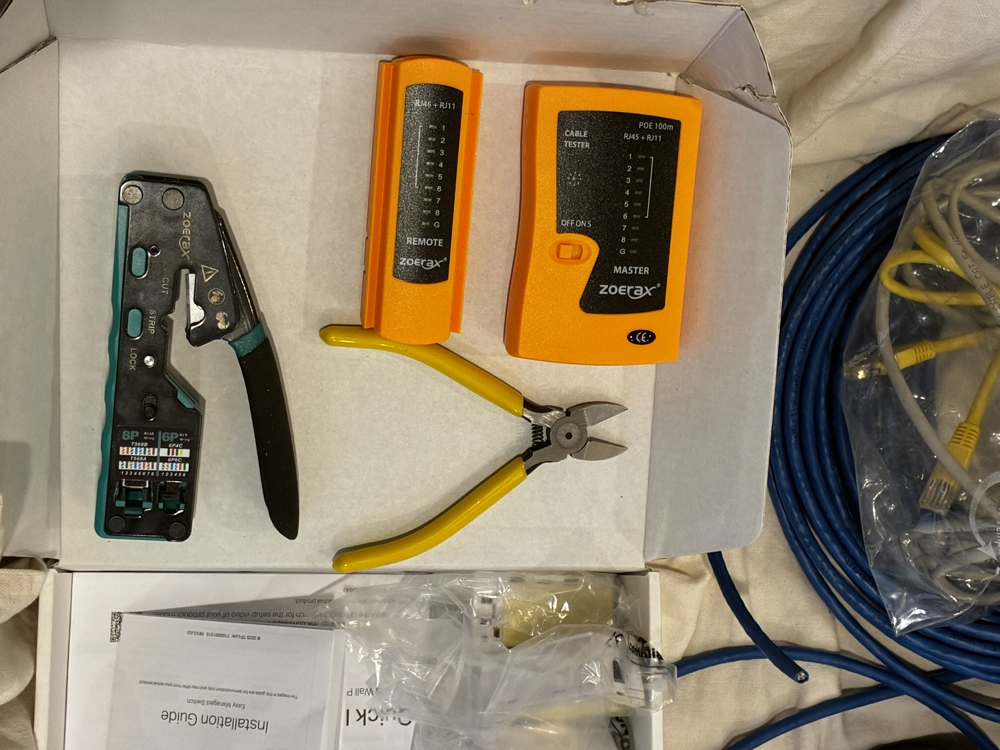
Some other parts and tools I bought:
- 100’ of unfinished Cat 6 cable
- 25’ long finished Cat 6 cable
- A bag of RJ45 pass through connectors
- Cat 6 junction boxes to connect a new cable to the existing cables
- Cable staples
- Low voltage wall mounting hardware, including brush plates
- A sheetrock saw
- Two sheets of plywood, cut into twelve 2x4 pieces
- A protective utility coverall (for working in the attic)
- Plug duct seal compound (to seal the hole between the attic and wall cavity)
Things I already had:
- A cordless drill
- Narrow bits (for drilling a few pilot holes)
- Large 3/8" drill bit (for passing Cat 6 through the framing)
- An old broom (for clearing attic insulation)
- A bright flashlight
- 12’ tape measure (which got lost in the attic)
- A magnetic stud finder
- Phillips head screwdriver
- Pocket knife with scissors (good for cutting zip ties and packaging)
- Respirator (for working in the attic)
- Mechanical pencil, ruler, and a bubble level (for marking where to cut the sheetrock)
- Broom and vacuum (to clean up the dust from cutting sheetrock)
- A yardstick, a metal hook, and some electrical tape (see below)
- A pocket mirror (with which I tried to see my dangling ethernet cable, but failed)
I split the project into six parts.
Part 1: Preparation
I planned the whole project out in advance. It needs some specialized parts (like the Omada gear), and it can be cheaper to buy online than in a local retailer. I wanted to have all the parts and tools at the start, so I could start working and not get stuck midway through.
I had some chats with Gemini to validate some of my assumptions and get some installation suggestions. I think Gemini was the first place I heard of Omada, and it recommended the Cat 6 junction box, as well as mentioning the existence of a tone generator. As always - you have to validate anything you think you learn from an LLM before doing anything with it.
One of my neighbors is an electrician, and another used to be a carpenter. I double-checked some of my plans with them in case they were, well, terrible ideas.
I also watched a bunch of YouTube videos to try to learn specific skills or get more context on my project. Truly, I could not have done the whole project without YouTube.
- First Look at the TP-Link Omada EAP615-Wall Access Point
- Wiring Up Ethernet Plugs The Easy Way and Keystone Jack Install!
- The Most Detailed Brush Wall Plate Installation
- How To Fish And Pull Electrical Wire From Attic Or Crawlspace To Outlet! DIY Tutorial For Beginners!
- How to install cable pass through wall plate
- How to Punch Down a RJ45 Cat 6 Keystone Jack
- How to Use a Tone and Probe Set - I did not actually do this but I considered doing it
I also watched some videos specifically about working in an attic with blown-in insulation:
- Attic Blow In Insulation (has horror movie vibes)
- “How to Safely Walk in an Attic w/ Blown In Insulation” - DIY Tips & Tricks
- How To Remove Blown-in Attic Insulation - I did not do this, but I wanted context
I spent quite a bit of time on the planning. I tried to practice measure twice and cut once, but probably taken to extremes.
Part 2: Installing the switch
I did the easy part first: I mounted my ethernet switch in my closet, where all the existing Cat 6 comes out, and then I connected the switch to the AT&T fiber gateway. There was already an AC outlet in the media distribution box. It was formerly used to power an abandoned coax amplifier for cable distribution, which I removed. It’s annoying that it just sat there wasting power for the past several years.
In between the AT&T gateway and the switch there needed to be a 25’ ethernet cable run, which had to cross through a closet wall. I used brush plates to make the wall crossing look pretty.
To install a brush plate: First you find the stud in the wall (so you can avoid hitting it by accident) and stay far from any AC power lines. It is a standard American house structure with sheetrock over wall studs every 16". Then you can draw the outline of the low voltage bracket on the wall, cut it out with the sheetrock saw, install the bracket (it has these little arms you can tighten down to fit it), and screw in the brush plate on top of that. Finally, sweep up all the sheetrock dust.
I ran the rest of the cable along the walls of the closet, securing it with cable staples in the corners.
When I was done, the media box looked like this:
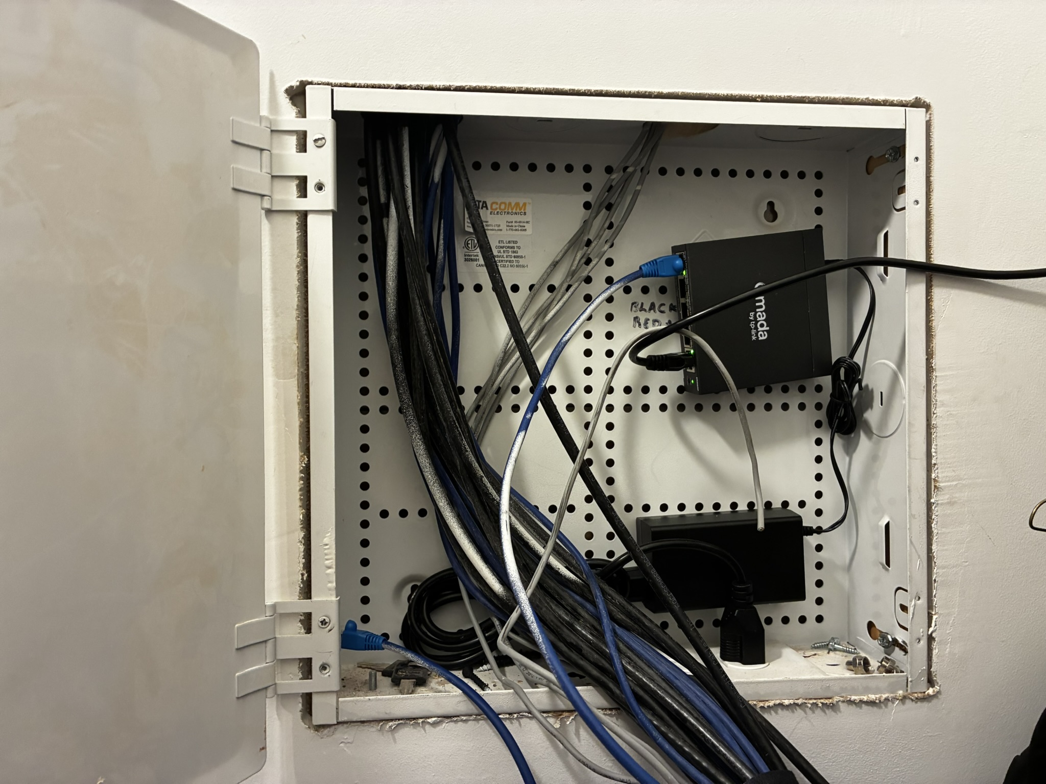
You can see the new cable entering from the right.
Lessons learned: Never buy a black ethernet cable if you are running it along an interior wall. Always use white so it blends in. Oops.
Part 3: Terminate all the bare Cat 6 cables
The media box had 11 unterminated Cat 6 cables running from elsewhere in the house. I put connectors on all the Cat 6 cable ends.
I thought, if I put connectors on every cable, it will be fast later to use the cable tester and trace which is which. It’s also a lot easier, if I ever want to use these cables in the future, if they already have connectors.
At first it’s hard to remember the wiring order for the RJ45 connector, as it seems very random (like any arbitrary standard). The crimping tool includes a handy RJ45 wiring diagram. You can either use T568A or T568B; I used T568B, which is supposedly more common.
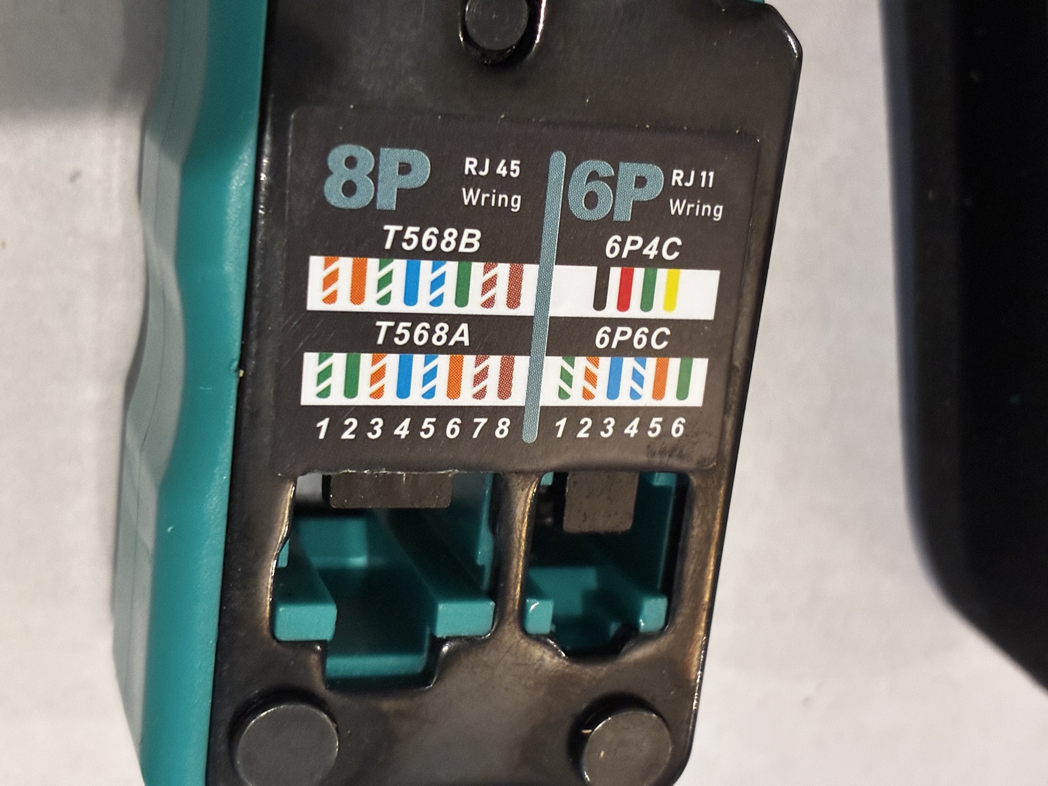
The first few connectors were a little bit tedious to install, since I had never done this before. It’s pretty finicky to unwrap the twisted pairs, cut out the little thread (why is that thread there??), flatten out the wires, and get them crimped down into the connector. But by the 11th connector, it started to get much easier.
Lessons learned: Practice really does make hard things easier. Also, now I can wire an ethernet connector.
Part 4: Splice a new cable into the attic
The work in the attic had a few different parts:
- Get all dressed up in a hilarious hazmat utility suit, boots, and a respirator. The loose insulation was not something I wanted to touch or breathe.
- Carry all the gear and plywood up the attic ladder (ugh).
- Use a broom to brush away the loose insulation and find the joists.
- Lay plywood strips across the joists so I could move around.
- Use the broom to brush away more loose insulation. Lay more plywood strips. Repeat.
- Trace the existing ethernet cables to see if any of them went to the room I needed. (Spoiler: None of them did.)
- Pick the closest ethernet cable to my destination, cut it in two, and splice my new cable into it with the junction box.
- Permanently mount the junction box to a joist so it wouldn’t get tugged around.
- Lay the cable so it ended exactly where it needed to go. Cut it so it had about 15-20’ extra length on the end.
- Drill through the joist and the top plate, and run the loose cable down into the wall cavity.
This phase was by far the hardest part of this project. It was physically strenuous, dark, confusing, and somewhat dangerous (because of the loose insulation and lack of an attic floor). It might have made sense to split it into a few different work sessions, but I really wanted to finish the project. I was physically exhausted after this part.
The inside of a Cat 6 junction box looks like this. It’s kind of cool. You have to attach the cables with a punch down tool.
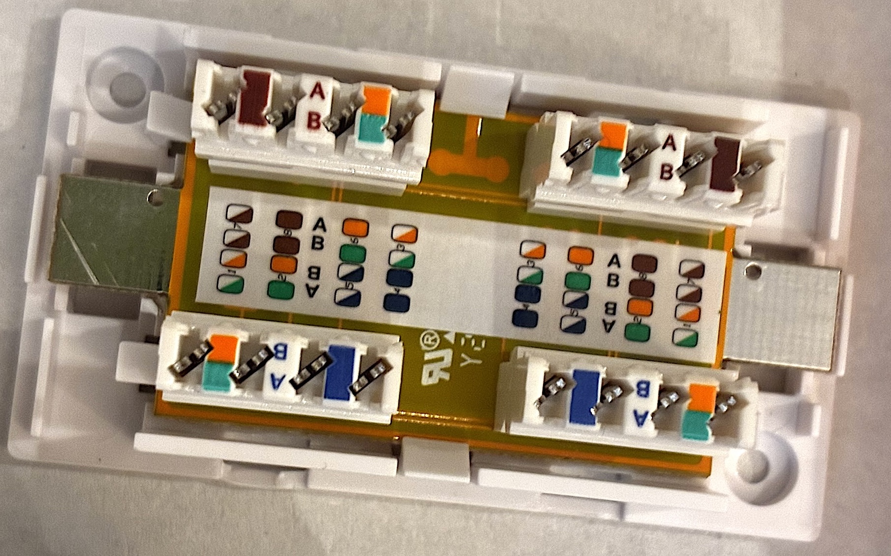
In general, the attic part was not super fun and kinda stressed me out, but I was also proud of myself after. It took me about two hours; I’m sure a professional would have done it much faster. It would have been easier with two people.
Part 5: Install the access point
I cut a hole for the access point in the wall, and then I fished the ethernet cable out of the wall cavity. I didn’t have the right gear for that (electricians use glow rods, but I didn’t), so I hacked my own tool by taping a big metal hook to the end of a flexible metal yardstick, and then I taped a metal poker to the end of the yardstick to make it longer. It was about 5 feet long and I just reached up into the wall cavity and hooked the ethernet cable.
When I got the cable out, it looked like this:
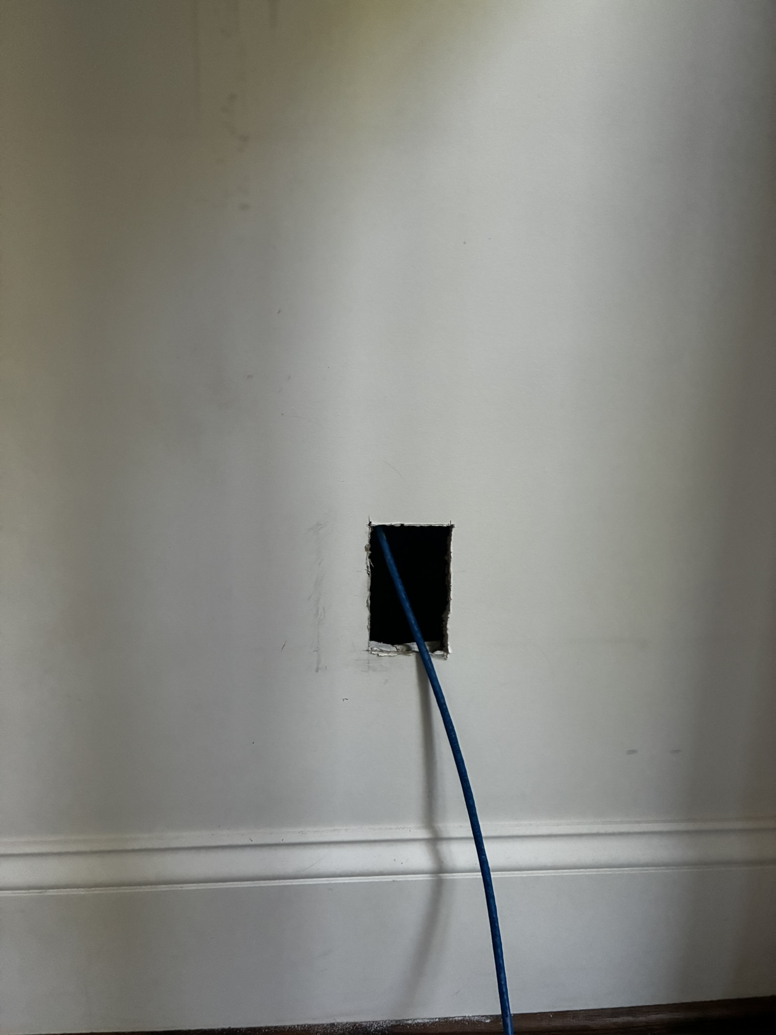
I put a connector on the end of the cable (it’s much easier to run unterminated cable as it can fit through smaller holes).
Then I used the network cable tester to check where the cable terminated downstairs. You attach one end of the tester to the upstairs part. Then you go down to the media distribution box and systematically plug each Ethernet cable into the other part of the tester until you see the lights light up. Hopefully there are no faults. I was worried about faults, as I have never done Cat 6 installation before.
Once I had a working cable attached back to the switch, I attached the Omada access point to the cable, installed the Omada mobile networking app, and configured the Omada gear. That part was a pretty slick experience.
I ran some speed tests against wired and wireless connections from the access point, just to make sure it actually worked. I saw transfer speeds around 450+ mb/s, which is lower than 1 gb/s, but much better than before.
Part 6: Cleanup
The attic still needs to be cleaned up a bit. The plywood should be removed, or at least the insulation needs to be readjusted. The hole between the attic and the wall needs sealing with duct seal compound. The wiring tools and spare cable need to be put away somewhere where I can find them again later.
Things I didn’t do
- Pay an electrician to do the work.
- Nail down the plywood in the attic (see below).
- Use a tone generator to trace cables through the wall (but it was very cool to learn this is possible).
Reflections
The architecture in the end worked out almost exactly as planned, but I did annotate the diagram with a few surprises.
There are a few things I wished I’d done differently.
- I wished I had a bright headlamp for working in the attic. It was stupid not to spend money on this. It was pretty awful to carry around a flashlight by hand, while crossing the joists and carrying sheets of plywood.
- I bought an Omada low voltage bracket to install the access point onto, but it turned out to stick out of the wall too much. I bought a replacement generic bracket that mounts into the wall and takes up less space.
- Walking on loose plywood sheets in the attic was super dangerous. If you step on the end where it sticks out past the joist, it will flip up into the air. Even if you know that, it’s hard to get it perfect.
- The drill bit was almost too short. It was very close. I didn’t realize there would be two 2x4s on top of each other at the top of the wall. I guess one was the top plate of the wall and the other was a joist on top of it. Something like that.
- It’s tough to find exactly the right spot in the attic to drill down into the wall. You have to find the right spot in the room underneath, and then somehow translate the spatial coordinates into something you can re-locate from above. Originally I measured distances from the end of the room, but it was impossible to triangulate precisely that way, because the finished wall downstairs isn’t exactly aligned with the framing above. In the end, I used a ceiling light fixture as a landmark, since it was clearly visible in both the attic and the room below.
Overall, I was pretty happy with this project. It’s cool to learn to do new things and gain new capacities. And the results are excellent.